Digital
CDHD - Communication and learning Helper for Deaf and Hearing people
Application for Hololens to aid Deaf people in learning and in communicating with hearing people.
Project developed during the Usability Engineering Masters course together with Pimchanok Sripraphan and Vivien Nwoye (2017).
Participated of the Accessathon - Hackathon for disabilities in Rhein-Waal University.
Fabricademy 2017
Final Project - Head wearable to assist people with paralysis

Defining the concept
In the university Rhein-Waal, the Fabricademy is also an Interdisciplinary Project with the theme of Fabrication for Care. For this reason, our projects had to be aimed in assisting people with physical or mental disabilities. The concept of my final project was developed by the fusion of two events that caught my interest.
From 24th to 26th of November, I participated of the Accessathon, a hackathon focused on disabilities, in which one of the invited lecturers was a researcher from our university BCI Lab. There I was presented the concept of BCI (Brain Computer Interface) and what it could do based on the projects done in the university. When thinking about possible sensors for my final project, this lecture came into my mind and the idea of using the brain waves as input was very exciting.
Researching about BCI
I researched on existing products using brain waves as input and found the following products that helped me to have an idea of what has been done and what could be done.

fig 13.1 - EEG in the BCI Lab. (source)

fig 13.2 - Controling robots with Open BCI.

fig 13.3 - Open BCI Ganglion board.

fig 13.4 - Brainduino 1.

fig 13.5 - Brainduino 2.


The headset and board are available for purchase and the code is available to be hacked to create new products.


fig 13.6 - Muse headset.
fig 13.7 - Muse app.
fig 13.8 - Neurosky headset.
fig 13.9 - Helmet with hacked Neurosky.
I also researched on disabilities, BCI and its applications and came up with the following list of ideas of applications for my final project:
-
Move a wheelchair / robots
-
Help in learning (detecting streess and focus)
-
Combine with breathing control
-
Detect and help Alzheimer
-
Help focus and relax through music background
-
Draw using only the mind
After this research, I arranged a meeting with Aya Rezeika of the BCI Lab, which is located in the city of Kleve, to present my ideas and understand better about the BCI subject and its realistics possibilities for this project. In this meeting I could understand the following points:
-
To create a BCI is needed a sensing unit and a processing unit. the sensing unit is an EEG (Electroencephalography) that senses the brain waves frequency through electrodes. The processing unit receives these signals and processes them into something readable.
-
There are dry and wet electrodes. The dry electrodes can only be used on bare skin, with no hair. The wet electrodes use gel which allows the signal to reach the electrodes through the hair.
-
Since the signal is very weak, the eeg needs amplifiers to improve the reading.
-
The easiest waves to identify are the beta and alpha waves. This last one spikes when the eyes are closed and when there is relaxation.
-
The more complex the application, the more wave channels and more electrodes are needed. For example, to move something foward, backwards, left and right, at least four channels are needed, one for each movement. However, to turn something on and off only one channel is needed to identify the presence or absence of signal.
-
Move cursor / control computer
-
Control a grabbing robot
-
Control music / Radio / MP3
-
Help reduce depression and anxiety
-
Help people with insomnia

fig 13.10 - How the BCI works.

fig 13.11 - Mindflex 1.

fig 13.12 - Mindflex 2.
After this meeting I understood that building a simple eeg that would have an "on and off" response is feasible for this project. It can be processed by an Arduino or Raspberry Pi and powered by normal batteries. An example given was the toy Mindflex. It is a simple eeg with which you can control the speed of a fan which regulates the height of a small ball by focusing and relaxing. However, most of the ideas listed previous were not within this limitation. With a simple eeg it was not possible to control complex movements and identifying emotions was beyond my understanding.
Meeting Rebecca
The other event that helped me defining my project was held in the 23rd of October, when we visited as a group the Caritas, a center that employs disabled people called Caritas, in the city of Duisburg. There we got to know Rebecca, a woman that has paralysis and cannot move or talk. She comunicates with the aid of a computer controled by the eyes movement with infrared sensor, with which she can type, browse the internet and perform many other fuctions.
After all my research on BCI, I decided to make a brain sensor wearable for people with paralysis as Rebecca, that are unable to move or speak. My idea of application was to create a brain sensor wearable to be used by the disabled person connected to a wristband to be used by the care taker. When the disabled user focuses, it vibrates the wristband meaning that the person is calling. That would allow the disabled person to be able to call the caretaker from distance.

fig 13.13 - Initial idea for application.
The EEG
The initial idea was to build one of the open source BCI boards I found during my research. I downloaded the schematic and unfortunately they were too complex for a beginner as I. As a second option, the university had accepted financing the board up to 200EUR. However, the Open BCI would take 3 months to reach me since it would be shipped from USA to Germany and with shipping cost it exceeded the financed value. I contacted the Brainduino and unfortunately it was still in production phase and not available for purchasing. The Neurosky is a ready headset which I could not dismantle to create my own wearable since it would be the university's ownership. As third option, I was presented by Aya to a DIY EEG Instructables which seemed feasible.
DIY EEG
First, I read the whole instructables and tried to understand its concept in general. It uses audio cable to connect the signal to the computer through the microphone port. Then, the waves can be seen using the software Processing. It includes only three electrodes: one as reference, one as ground and one as signal. After confirming that the components were within my reach I proceeded to buy all that was needed.
I purchased exactly the same components described, with the exception of one resistor that I could not find the same value on the website and the electrodes. I tried to order the metal cup electrodes online but had no success. The online store returned me saying they do not sell for personal use. Before trying to buy through the university I decided to buy disposable ones from Amazon, which had a faster shipping time, so I could start building the circuit sooner.
After receiving the components including the electrodes, I could not understand how to connect the electrodes to the breadboard. The plug had a diameter of 2 mm and I could not find a cable to purchase that would fit. I tried to cut the wire so I could connect it to the breadboard put surprisingly it was not a wire. It had the shape of a brush and since it was no metal it could not be soldered. With the help of Johnathan Yen, I solved the problem by removing only the plastic cover of the tip of the plug and soldered a wire to it. By doing so, all components were ready to assemble the circuit.
I started by connecting everything on the breadboard as indicated on the schematic of the instructables. I was having a lot of difficulty to connect everything and the amout of wires was really confusing. For this reason I was suggested to build a board directly, since most of the components were resistors and capacitors.
I decided to follow the suggestion and rebuilt the schematic on Eagle after a quick tutorial with Thu Ngyen. First, I copied the schematic as the original, adding the components available in the library and naming them and adding labels when necessary to make the drawing cleaner.

fig 13.14 - Metal cup electrode.

fig 13.15 - Disposable electrodes.

fig 13.16 - Electrode plug and its cut wire.

fig 13.17 - Soldered solution.

fig 13.18 - DIY EEG components.

fig 13.19 - Schematic of the DIY drawn in Eagle.

fig 13.20 - Components arranged in Eagle.

fig 13.21 - Finalized board, with components swaped for one with big pads.
Next, I uploaded the image file of the traces on the website fabmodules.org where I selected the following settings:
output format: Roland mill (.rml)
process: PCB traces (1/64)
machine: MDX-40
speed: 4 mm/s
x, y, z = 0
cut depth: 0.1 mm
tool diameter: 0.2 mm
number of offsets: 4
offset overlap (%): 55
For cutting the board out of the copper plate the settings were the following:
output format: Roland mill (.rml)
process: PCB traces (1/64)
machine: MDX-40
speed: 6 mm/s
x, y, z = 0
cut depth: 2 mm
tool diameter: 1 mm
number of offsets: 1
offset overlap (%): 50
After that, I clicked on calculate and then saved the file on a usb stick. To prepare for the milling, the copper plate must be well fixed. Then on the printing settings it is necessary to adjust the origin coordinate (0,0,0). There are 3 speeds available to move the tool on the space. Since the tool is very delicate, the moving must be very careful. For adjusting the Z axis there is a sensor available, which can give a more precise value.
After the milling was over, some of the traces were not completely milled due to a slight inclination on the plate. As a suggestion of Ahmed I erased in Photoshop the traces that didn't need a second milling (fig 13.23) and send the file to mill again. This time unfortunately I configured the wrong speed and the fine tool broke.
When the second milling was successful I proceeded to punching the holes in the board with a very fine drill. Next, I soldered all components to the board.
I tested all connections with the multimeter and noticed that some of ground areas were not connected. To cope with this problem I built "bridges" with the wires. After assuring that all connections were connected I started the testing.
As the instructables recomended, I tried to read the values with Processing software. Unfortunately the code provided was not working. I had to fix some parts and did many more attempts not only with processing but also with the Arduino. I also tried to play changing the potentiometer but with no results. The board for some reason was reading the environment sound but the electrodes had no signal.
To fix the problem I visited again the BCI Lab of the university. There Aya helped me once again and made some tests witht their equipment. The conclusion was that probably the amplifiers were already broken, since they are very delicate. She suggested not to solder the components directly but to solder sockets (fig 13.29) that would fit the amplifiers, allowing them to be replaced easily. I ordered them and new amplifiers online but unfortunately they would take to long to be delivered.

fig 13.29 - Amplifier socket.
Interview with Rebecca
Meanwhile the DIY BCI board was being built I scheduled interviews with Rebecca to understand her needs better and validate the need for the brain wave sensor wearable I was developing. I used the following questions as guidelines but as the interview developed new questions were raised:
What are the difficulties in her daily routine?
What are her wishes and needs?
What are her restrictions and possibilities in communication and movement?
Tobias, which is her fiancé who lives with her, responded on her behalf some of the questions and others were asnwered by her with a smile, a laugh or frowning. He introduced me the devices she uses and their functions. The idea of having a bracelet that would allow her to call him from a distance by concentrating was very well appreciated.
Another suggestion given by him was to control electrical devices. He explained me that she uses a device connected to her computer which allows her to turn on and off any other electronic device plugged in the first one. With this she is able to interact in the kitchen, baking cake together by controlling the blender and even work with the sewing machine. This device is connected to the computer with an audio cable.
Despite that, Rebecca doesn't like to use the computer very often because focusing on the screen is very tiring for her. He suggested to substitute the computer for the brainwaves which would give her more flexibility and less dependancy on the computer.
I decided to work on this last idea and connect the wearable to this device and for that Tobias lent me one device that was not being used for testing purposes.
Then I tried to arrange the components in order to occupy the less space as possible but still allowing me some space to handle the soldering. After arranging, I was advised by Wei Cheung to swap the components that had small pads to bigger pads to facilitate the soldering. I changed all the components that had small pads to jumpers with bigger pads and, since there were many components that were connected to ground I made a common ground and rearranged the components. I was also advised to draw peferably straight paths and not tilted ones to facilitate the milling.
After the board was ready, I started the preparations of the file to mill with the help of Ahmed Belal.
First I changed the settings to display only the information needed disable the viweing of the names, for example. Then, with the contour of the board selected, I increaded the isolation to 0.6096 in the properties window. After that I exported the file as an image (monochrome option checked) with 1500 dpis.
Next, I opened this image in Photoshop and created a copy with the paths erased leaving only the shape of the board. The milling machine recognizes the contrast of black and white. It is necessary to create a copy of the file for milling the contour of the board with a thicker drill which will cut the board out of the copper plate.


fig 13.22 - Images black an white to be read by the milling machine. (circuit and board)

fig 13.23 - Board being milled.

fig 13.24 - Milling corrections.

fig 13.25 - Milled board.

fig 13.26 - Punching holes with the drill.

fig 13.27 - All components soldered.

fig 13.28 - Testing the DIY BCI board with no success.


fig 13.30 - Me and Rebecca.
fig 13.31 - Rebecca and Tobias using the computer that can be controlled with eye movement.
fig 13.32 - Device used to control other electronic devices.

fig 13.33 - New use case suggested by Tobias.
The MYO sensor
After the unsuccessful attempts to use the EEG, because of the time constraints, Adriana Cabrera suggested me to build the prototype using muscle sensor. I made some tests with the sensor to see it working and tested the code using an LED as shown in the fig 13.13. Then I tried to read the values of the movement of the muscles from the forehead, which was also successful (fig 13.35).
As the next step, I connected the device to the computer through an audio cable and the code also worked successfuly. By changing the values capted by the myo sensor a fan turned on and off. (fig 13.36)
Next, I changed the code to turn on the fan once the values went up and down and to turn off when the up and down movement is repeated. This is necessary otherwise, in order to keep the fan on the muscle has to be continuously stresses, which is not confortable for the user. The chance can be seen in fig 13.37.
fig 13.34 - First tests with myo sensor.

fig 13.35 - Testing of the myo sensor with the muscles on the forehead.
fig 13.36 - Testing of the myo sensor with electronic devices.
fig 13.37 - Changing the code to turn on and off an LED with up and down movement.
Designing the wearable
After the code was done, I tested it with the Arduino Pro mini and confirmed that it could be used on the wearable. I measured all the necessary components and designed the headband in Illustrator.

fig 13.38 - Design scheme in Illustrator.
The idea was to fit all hard components in a 3D printed case positioned behind the ear, while only the myo sensor and the Arduino would be built in soft circuit in textile on the forehead area, to fit to the curvature of the head. I also considered using elastic textile to add more flexibility and adapt better to different head sizes.
The myo sensor uses pads with glue to read the muscle signals. For the wearable I wanted to substitue this pads for conductive textile. To have a good reading it is necessary to have a tight contact with the skin. In addition, it was important that it should be confortable to wear. For the reason I created new pad with semi-conductive foam covered with conductive textile, which would allow the pads to sit better on the round forehead.

fig 13.39 - Construction of the sensor pads. On the left, the orinal one removed.
To design the components case I used the 3D software Cinema 4D. I considered a lithium rechargeable battery 3,5V to be used as power source. The Arduino needed 5V so I used a voltage convertor to transform the 3,5V to 5V. The scheme in fig 13.38 shows how it was connected to the circuit.
To connect the wearable to the electrical device I needed an audio jack to plug the audio cable. Luckly my friend Johnathan Yen was throwing away a broken speaker and let me take the audio jack from it's board. He also has great soldering skills so he also removed it from the board using a sucction tool. The trick was to add more solder, heat it and remove again the solder using the sucction tool, with a lot of patience.
The audio jack should be positioned inside the components case too, in a way that the cable would be hanging behind the ear, in order to bother the user the least as possible. I designed the case to fit all components and wires tightly, a lid to close it and a grip to hold the textile part.

fig 13.42 - First 3D model of the components case.
The initial idea was that the wearable would be held by both ears and not have a band going around the head. After I 3D printed though I noticed that it would be impossible. For the wearable to stay fixed on the ears, the front part should be hard and not flexible.
To fix this problem, I added on the case a handle in which I could sew a textile strip that would go around the head. I also made improvements on the design, to fit the case better behind the ear, using the glasses as reference. I also wanted to change the color of the PLA to white but unfortunately we had no other color available in PLA. There was white color only for ABS but I was advised that 3D printing in ABS had more complications. It needed more temperature so, apart from increasing the bed temperature, I also covered the open windows of the machine with cardboard to keep the temperature from dropping.
After several failed attempts, I gave up on using the ABS and lucky found a white PLA to use.
Furthermore, I added some holes on the connection of the case to the textile so them could be sewed to each other because the grip I designed was not secure. This hole however were not well defined after 3D printed so I punched them with the drill.

fig 13.40 - All pads substituted.

fig 13.41 - Board taken from the broken speaker, containing the audio jack.

fig 13.43 - Johnathan Yen removing the audio jack from the speaker board.

fig 13.44 - 3D printing the first version with PLA.

fig 13.45 - Improved 3D model of the components case.
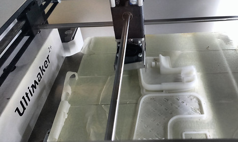
fig 13.46 - Attempts with ABS were deforming.

fig 13.47 - All 3D printed attemps of the component case.


For the forehead part I chose the felt because of it's stability. I laser cutted it using the file I drew in illustrator. To build the soft circuit I wanted to embroider it using the embroidering machine but I didn't know how to fix the textile that was already cut. Adriana that the idea of embroidering first it's trace on the adhesive paper. Then we could fix the cut felt part in the right position and embroider the circuit with conductive thread. The idea worked very well.
fig 13.48 - Embrodering the trace of the front part.
fig 13.49 - Embrodering the circuit with conductive thread.
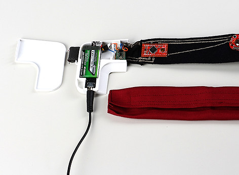
I then sew the myo sensor and the Arduino Pro Mini if the textile assuring the connections with the multimeter. Then I added the elastic parts on both sides. The one that contained part of the circuits I added paths of conductive thread and the elastic conductive textile Shieldex Balingen.

fig 13.50 - Finished forehead part.
After that, I proceeded to built the hard part of the circuit that would be placed inside the case. Adjusted the voltage convetor using a screwdriver and a multimeter. Then I soldered wires to the audio jack and the voltage convertor. To connect all these wires to the circuit properly, I used a piece of board with conductive holes suggested by Adriana (fig 13.51). Johnathan helped me again with the soldering, due to my lack of skill.

fig 13.50 - Finished forehead part.

fig 13.51 - Johnathan Yen soldering the wires on the board.
To cover the electronics on the forehead I designed a textile cover closed with velcro. This would avoid the contact of the circuit with the skin (apart from the sensor), allow it to be washed and add a customization feature. The idea is that the user can have many different cover and match the color and textiles with their clothes. I sewed narrowing the ends in order to look puffy and add some style to the design, not looking like a simple headband.


fig 13.53 - Cover finished.
fig 13.52 - Cover with velcro.
fig 13.54 - A ring was added to right end to allow the closure of the headband.
Next, I sew the forehead part to the case using the holes punched before. To close the circuit I sewed the soft circuit to the little board with holes placed inside the components case. To finalize the prototype, I added a strip with velcro to be adjusted and fixed on the head. Below are the final results.